In order to adapt to the development of an aging society and accelerate the landing and application of small household service robots, I will develop a small autonomous home inspection and security robot. I named it White Egg No.1. Its core lies in its ability to autonomously cruise within the home environment while monitoring abnormal conditions in the home environment (such as elderly falls, stranger intrusion, harmful gas concentration, flammable gas concentration, smoke concentration, fire situation, etc.). It can also serve as the core of the smart home to connect various peripherals (air conditioning, lighting, curtains, sleep detectors, etc.), facilitating unified management, scheduling, and control of smart home equipment;
I will record and share the entire development process. Provide documentation and source code for circuit design, shell design, algorithm design, and code implementation, facilitating communication and secondary development. The code for the entire project can be found on my GitHub address: https://github.com/softdream/robot_projects , will be continuously updated in the future.
In this article, we will introduce the overall functions, design ideas, and software and hardware framework of robots to give you a general understanding. Then, in subsequent updates, we will introduce the specific implementation of each functional module.
First, take a look at the appearance of the robot, as shown in Figure 1:
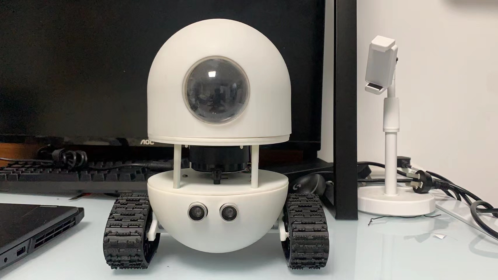
图1. 机器人外形
It can be seen that the robot adopts a typical two wheel differential structure, which is characterized by simplicity, ease of control, and a more cool tracked design. Except for the ready-made tracks, all other parts of the robot are made using 3D printing. The STL model files of each part are also uploaded to the Github warehouse, and you can directly download and use them. If conditions permit, you can also redesign the shape yourself.
The hardware structure diagram of the robot is shown in Figure 2:
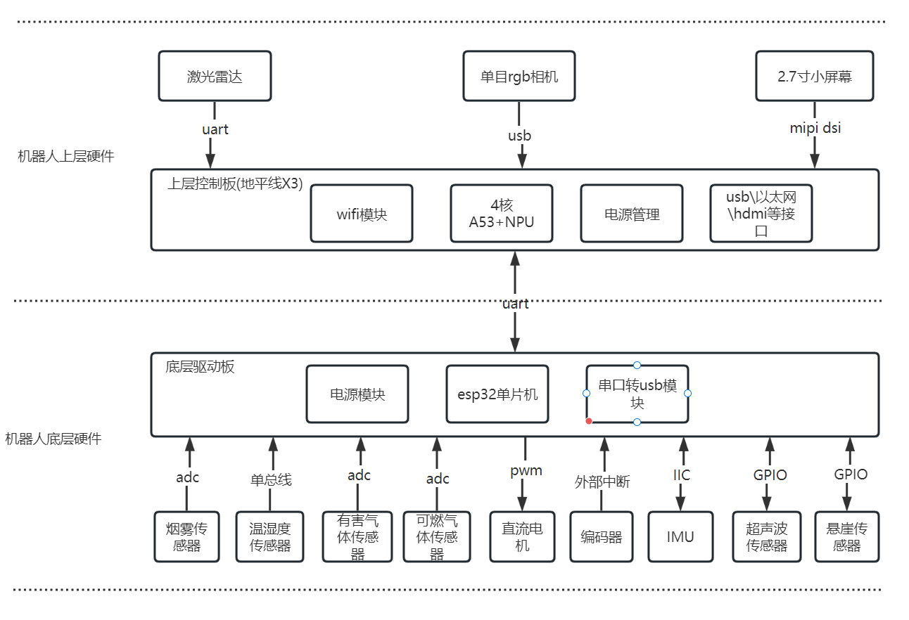
The hardware design of the robot adopts a layered design approach, using two controllers: for the data collection of various sensors at the bottom layer and the control of the robot’s motion part, a low-cost and relatively low performance microcontroller is used, while for the upper layer, the algorithm operation of the robot needs to be completed, and high computing performance devices such as cameras and LiDARs need to be driven. Therefore, the microcontroller is no longer able to meet the requirements, and a powerful embedded SOC needs to be used to complete it. I used the X3 Pi from Horizon here, which has a main frequency of up to 1.2GHz and four A53 cores. It is equipped with a WiFi module and, more importantly, an NPU computing unit with a computing power of up to 5Tops. In subsequent use, it can be used in conjunction with a monocular RGB camera to perform various functions such as personnel detection and human posture detection.
For the underlying controller, it mainly consists of three modules: power module, serial to USB module, and ESP32 microcontroller. The function of the power module is to stabilize the input battery voltage to 5V and 3.3V. The serial port to USB module is mainly used for program downloading and communication, while the ESP32 microcontroller, as the control core, is mainly used to drive the following hardware units:
a. Smoke sensor: Using ADC to collect data from this sensor, it is mainly used to detect indoor smoke concentration and for fire monitoring.
b. Harmful gas sensor: ADC is used to collect data from this sensor, mainly used to detect indoor harmful gas concentrations (which can detect methane, butane, propane, alcohol lamp gas concentrations).
c. Combustible gas sensor: Using ADC to collect data from this sensor, it is mainly used to detect indoor combustible gas concentration (which can detect gas concentrations such as carbon monoxide and liquefied natural gas).
d. Temperature and humidity sensor: uses the single bus protocol defined by the sensor to collect its data, mainly used to detect indoor temperature and humidity information.
e. Two DC motors: model 370 DC deceleration motor, used for the walking mechanism of robots, using PWM square wave signal to control the motor speed.
f. Two AB phase encoders: directly integrated at the tail end of the 370 deceleration motor, used to measure the motor speed using the large M method.
g. Inertial Measurement Unit (IMU): Model MPU6050, this IMU inherits a three-axis accelerometer and a three-axis gyroscope for robot attitude measurement, and uses the IIC protocol to read its data.
h. Ultrasonic sensor: Due to the low resolution of LiDAR, in order to prevent some obstacles from not being detected, an ultrasonic sensor has been installed to assist in obstacle avoidance.
i. Cliff sensor: Actually, it is an infrared ranging switch used to detect steps and prevent robots from falling.
The circuit diagram and PCB file of the underlying controller will also be uploaded to the GitHub repository, which can be directly downloaded and sent for sample use.
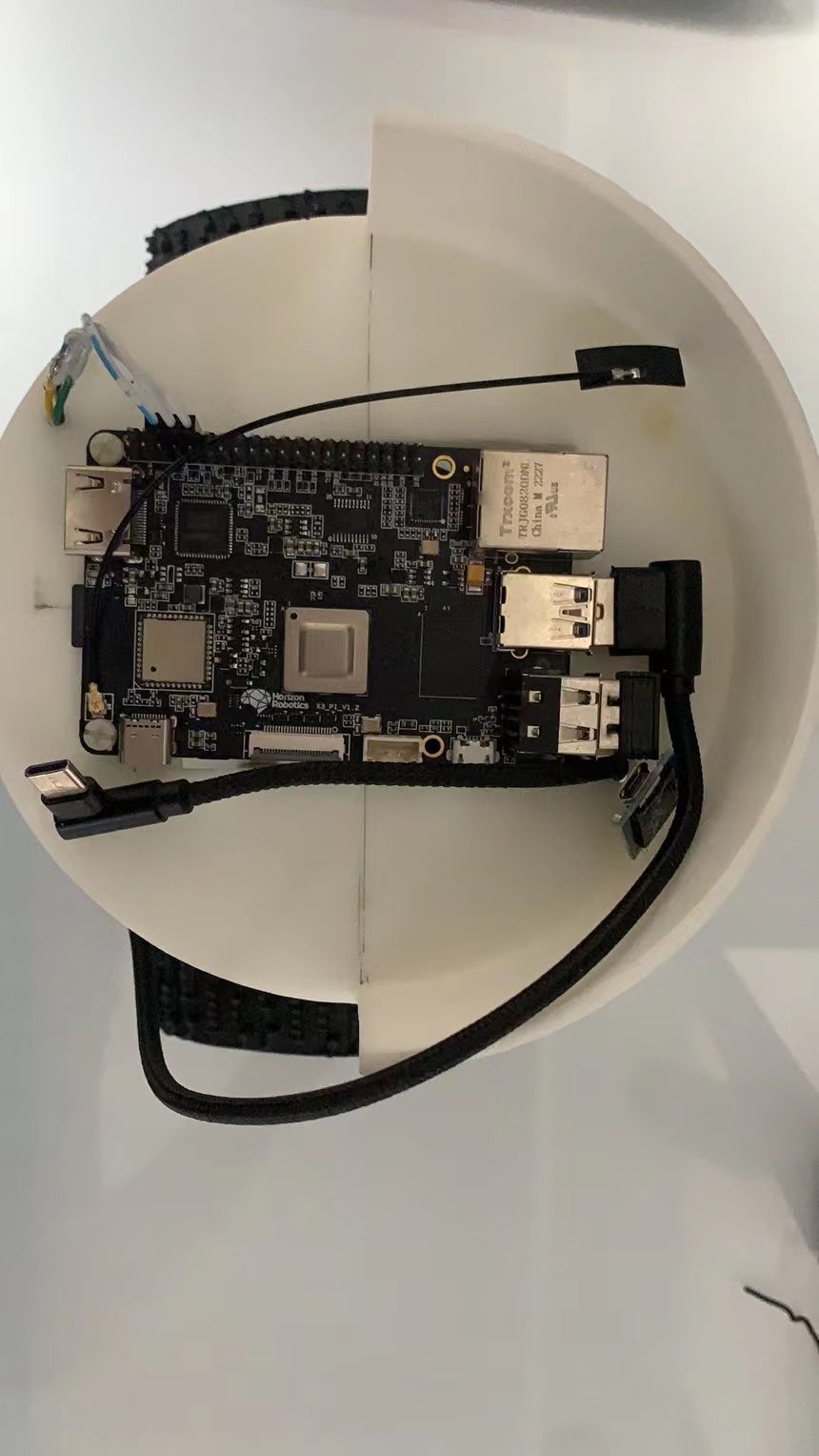
For the upper controller, the Horizon X3 development board was directly used. The development board has integrated commonly used HDMI, Ethernet, USB and other interfaces, as well as built-in WiFi modules, which can be used directly. Its core chip is used to run various algorithms and drive peripherals such as cameras, LiDAR, and screens:
a. Single lens RGB camera: This camera is used to support applications such as human body recognition and posture detection.
b. Single line LiDAR: Using the mini M1C1 LiDAR from Guoke Optics, with a frequency of 10Hz, each frame of data contains 380 ranging point information, used for SLAM (simultaneous map construction and positioning) and autonomous navigation functions of robots.
c. 2.7 inch RBG screen: used to display robot expressions and provide certain human-machine interaction functions.
In addition, the upper controller communicates with the lower controller using a serial port protocol. The lower controller sends the collected sensors to the upper controller for further processing through the serial port, while the upper controller sends control instructions to the lower controller through the serial port for driving robot motion.
The Horizon X3 development board used by the robot is shown in Figure 3:
The physical diagram of the bottom control board is shown in Figure 4:
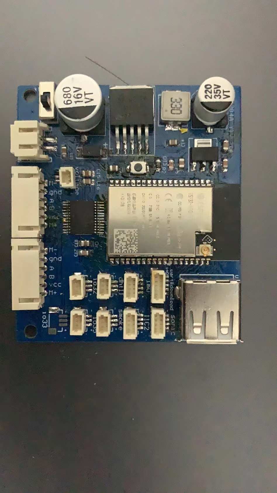
图4. 底层驱动板实物图
The software part of the robot is the core of the entire project and also the area with the highest development workload. It should be noted that this project does not use ROS system and tries to avoid using third-party libraries. In this project, only Eigen and Opencv libraries are used for all algorithms. Although this approach increases the difficulty and workload of the work, it is very beneficial for learning. In the subsequent updates, we will provide a detailed introduction to the design principles and code implementation process of each part, in order to help everyone better learn the principles of robot algorithms.
Project program development environment:
- Horizon X3 development environment
a. Operating system: ubuntu18.04 \ ubuntu20.04;
b. Language standard: C++17;
c. Compiler: g++version 7.5 or above;
d. Package management tool: CMake 3.16 or higher version;
e. Third party libraries: Eigen3, opencv3.4 or higher versions;
- Development environment for the underlying driver board
a. Integrated development environment: Arduino IDE;
b. Lexin ESP32 development library;
- Desktop application and WeChat mini program development environment
a. Desktop: QT5 and QT Creator integrated development environment;
b. WeChat Mini Program: WeChat Developer Tool;
The software architecture of the first version of the robot is shown in Figure 5:
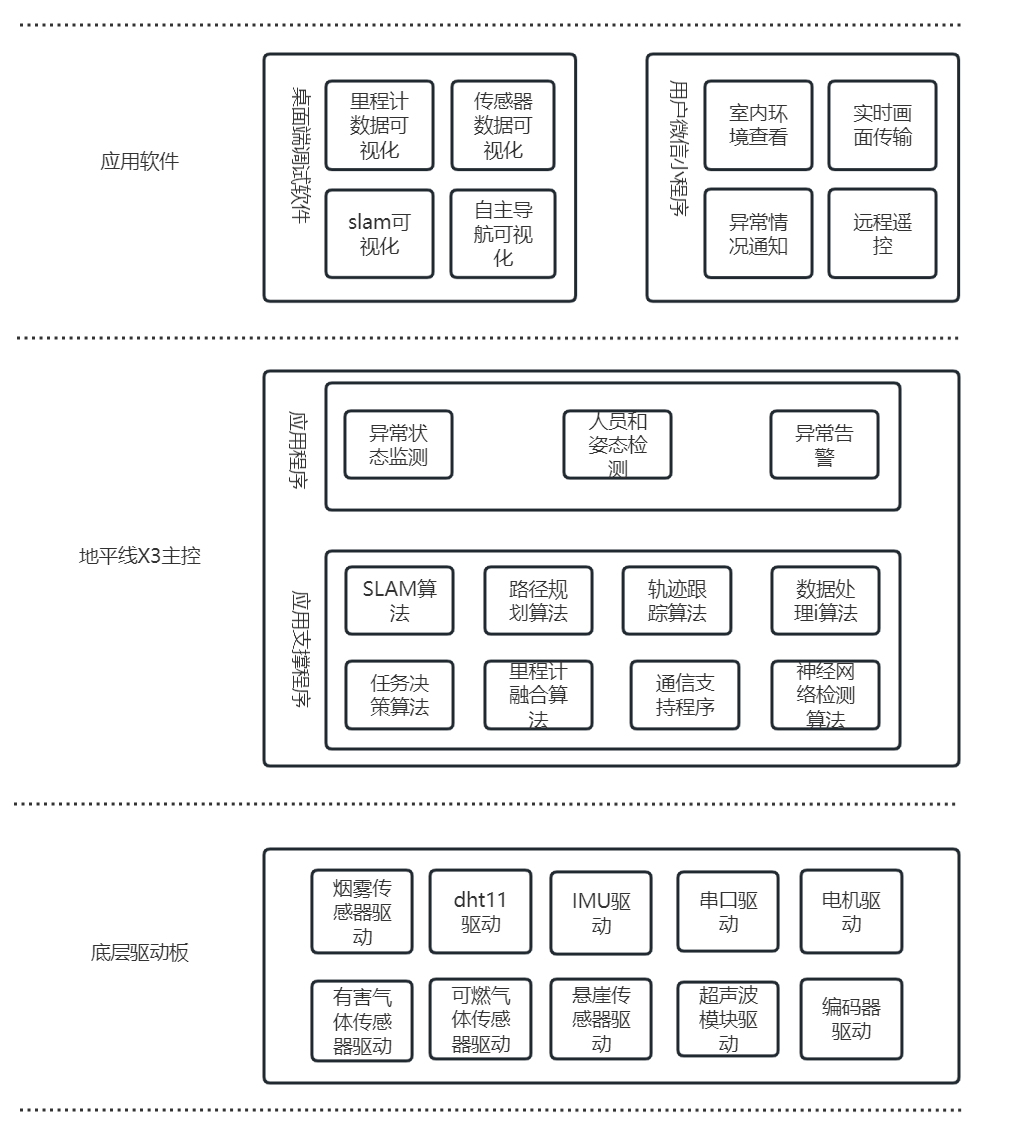
In the underlying driver board, the main functions are to collect and process data from various sensors. After obtaining this information, the underlying driver board will directly upload it to the X3 main control through the serial port for further processing. At the same time, the control function of the motor is implemented in the bottom driver board. After receiving the control instructions (mainly linear speed and angular speed) issued by the X3 main control, corresponding PWM square wave signals will be generated to control the speed of the two DC motors, allowing the robot to complete movement.
There are mainly two types of programs in the X3 main control: one is the basic program used for application support, including SLAM algorithm, odometer fusion algorithm, path decision algorithm, etc. These algorithm programs are the support for autonomous mobile robots and the key to enabling robots to move autonomously. Another type is some customized applications based on the above algorithms. As this robot is mainly used for patrol and security checks, only customized application functions are made for this area. Users can make changes as needed during secondary development.
In the next article, I will provide a detailed introduction to the circuit design scheme of the robot’s underlying control board, as well as the principles and implementation of its program design.