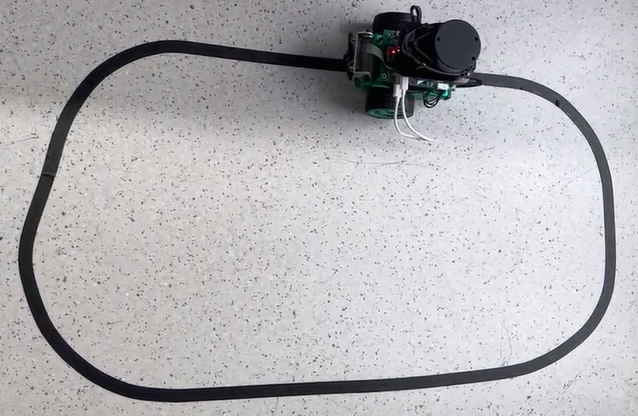
Line patrol task, that is, the robot car can autonomously follow a guide line to move forward, the guide line to the left, the car also followed to the left, the guide line to the right, the car followed to the right. This task is a relatively basic task in wheeled robots, and there are many ways to achieve it, such as:
By installing multiple photoelectric sensors (gray scale sensors), judging whether the sensor is on the line according to the return value of the sensor, and then adjusting the robot movement direction;
The position of the line in the image is obtained by camera based on traditional image processing methods such as edge detection, and then the direction of robot movement is adjusted.
When the lighting environment and the site change, it is generally necessary to adjust the threshold and test the image repeatedly to achieve better recognition results. Would it be possible for a robot to adapt to changes in its environment without having to adjust the threshold manually? Convolutional neural network (CNN), one of the most successful applications of deep learning algorithms, has good adaptability and robustness. In recent years, with the rapid development of chip technology, CNN reasoning can be carried out on the embedded end. This paper attempts to realize the position perception of the guide line in the line patrol task by CNN.
The effect is as follows:
Design
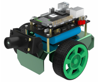
The OriginBot kit is selected here. The car body has two driving wheels and one driven wheel, and the rotation control is carried out through the differential speed of the two driving wheels. The MCU module is mainly used for the motor motion control of the car to communicate with the main control X3pi through the serial port.
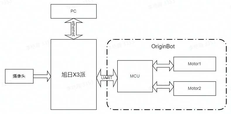
The main controller is selected as the Rising Sun X3. The board is the same size and interface as the Raspberry PI, which can easily be compatible with Raspberry PI peripherals, and has 5Tops computing power to easily perform complex CNN tasks. CPU 4*A53 + 4G LPDDR4 can easily handle complex robot tasks, Gigabit Ethernet and wifi ensure real-time and flexibility of big data communication. The MIPI CSI interface allows access to low-cost cameras.
The whole system is shown in the figure above. Asahi X3 obtains the environmental data in front of the car through the camera. The image data is deduced through the trained CNN model to obtain the coordinate value of the guide line, and then calculates the motion mode of the car according to certain control strategies.
PC is used for data annotation and training. In order to improve efficiency, X3 sends pictures to PC through Ethernet for annotation.
Software engineering
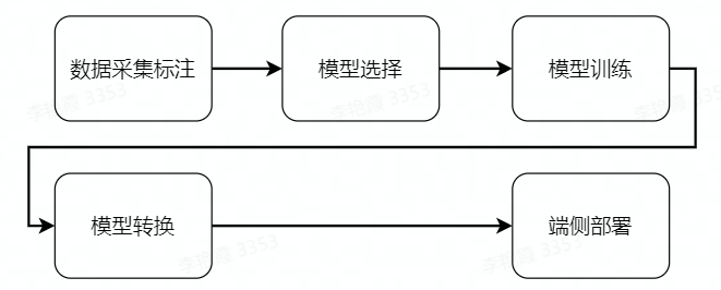
The whole software engineering consists of 5 main steps:
(1) Data acquisition and annotation: obtain the corresponding data according to the task objective and annotate it for model training;
② Model selection, according to the task objectives to select the appropriate model structure to ensure that the performance and accuracy can meet the needs;
(3) Model training, using marked data to train the model to achieve satisfactory accuracy requirements;
(4) Model conversion: Using AI toolchain to convert the trained floating point model into a fixed point model that can run on the Rising Sun X3 pie;
⑤ End to side deployment, run the converted model on the X3pi of the rising Sun, get the perception result and control the robot movement.
In order to simplify feature development, maintain scalability, and take full advantage of the 5T computing power provided by the Rising Sun X3, we selected TogetherROS as the underlying software for feature development and expansion. Its main features are as follows:
TogetherROS is compatible with ROS2 Foxy versions and is committed to building a collaborative, optimised, rich and easy to use robot operating system.
TogetherROS provides the hobot DNN feature pack to support easy deployment of the CNN model;
TogetherROS 'hobot Sensor capabilities and cross-device communication capabilities simplify data acquisition and annotation;
TogetherROS includes a wealth of sample code to facilitate future robot feature extensions and upgrades.
line_follower
├── 10_model_convert
│   └── mapper
├── line_follower_model
│   ├── line_follower_model
│   ├── package.xml
│   ├── resource
│   ├── setup.cfg
│   ├── setup.py
│   └── test
└── line_follower_perception
    ├── CMakeLists.txt
    ├── include
    ├── package.xml
    └── src
Among them:
(1) The 10_model_convert folder is used to store the code and configuration related to the floating point model, and all the contents of the folder need to be run in the AI toolchain docker;
The line_follower_model folder is used to store the content related to model training, such as data annotation, model training, and generating onnx model. All the contents of this folder run on PC;
③ The line_follower_perception folder is used to store the code running on the X3PI, which can be compiled on the board or generate the package running on the X3pi through cross-compilation.
Data acquisition and annotation
Model training can’t be done without data acquisition and annotation. Here, we can build a simple data acquisition and annotation system on a PC using the mipi camera image acquisition capabilities and cross-device communication capabilities provided by TogetherROS’s hobot Sensor. The workflow of the entire data acquisition and annotation system is as follows:
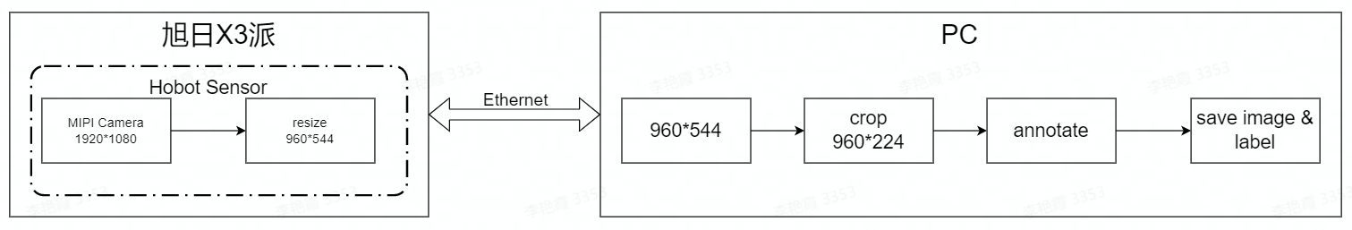
① Hobot Sensor is used to obtain 1080P images from MIPI Camera;
(2) Scale the MIPI camera image from 1920*1080 resolution to 960*544 resolution and publish it through topic: image_raw;
③PC subscribe to topics published by the Rising Sun X3 party through ROS2 Foxy, and obtain 960*544 resolution images in real time;
(4) PC clipped the central part of the Y direction of the 960*544 image to get a 960*224 resolution image;
⑤ Use opencv to label the clipped image;
⑥ Save the annotation results and corresponding images.
The completion code of this function is located in line_follower/line_follower_model/line_follower_model/annotation_member_function.py, where steps 1 and 2 are implemented on the Rising Sun X3 pie. Step ③-⑥ is implemented on the PC. Let’s look at the implementation of each step in detail.
Steps 1 and 2 need to be done by modifying the TogetherROS Hobot Sensor configuration file to create a working directory in the /userdata directory, using my_ws as an example:
mkdir -p /userdata/my_ws
cd /userdata/my_ws

mkdir launch

cp /opt/tros/share/mipi_cam/launch/mipi_cam.launch.py launch/mipi_cam_capture.launch.py
Here the modification points are as follows:
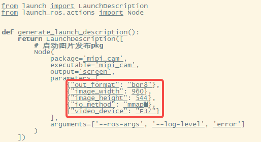
① Change the output image format to BGR8, that is, set the out_format in parameters to “bgr8”.
② Change the message communication mode to non-zero copy mode, that is, set io_method in parameters to mmap.
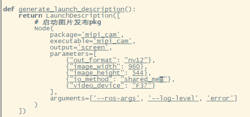
The modified mipi_cam_captur.launch.py file is as follows. The current output image resolution of Hobot Sensor is 960*544, and the selected camera module is F37:
Step 3: PC subscribe to the topic published by the Rising Sun X3 party through ROS2 Foxy, and obtain 960*544 images in real time. You need to create a subscriber. The ImageSubscriber class is created here to implement the Image message subscription. In the initialization __init__ function, a subscription node is created by self.create_subscription, where image is the type of the subscription message and ‘image_raw’ is the title of the subscription. self.listener_callback is the callback function, and 1 is the number of cached messages. Here you need to use the latest image every time, so configure the cache to 1.
import rclpy
from rclpy.node import Node
from cv_bridge import CvBridge
import cv2 as cv
import uuid
import os
import numpy as np

from sensor_msgs.msg import Image


class ImageSubscriber(Node):

  def __init__(self):
    super().__init__('ImageSubscriber')
    self.subscription = self.create_subscription(
      Image,
      'image_raw',
      self.listener_callback,
      1)
  def listener_callback(self, msg):
Whenever the subscribe node receives data, it triggers the callback function listener_callback, which can be used to get the image sent by X3 and do further processing.
Step 4, in the listener_callback function, the center part of the Y direction of the 960*544 image to be obtained is cropped to get the 960*224 image. First of all, we need to use cv_bridge to convert message image into opencv image format, and then use opencv crop function to crop. Here the x direction remains the same, and the y direction retains only the middle 224 rows.
  def listener_callback(self, msg):
    keyValue = cv.waitKey(1)
    if keyValue == 13:
      captureImage = self.bridge.imgmsg_to_cv2(msg)
      cropImage = captureImage[160:384,:,:].copy()
Step 5: opencv is used to mark the clipped image, that is, the center coordinate of the guide line in the middle area of the vertical direction of the image is given. In order to improve the convenience of annotation, the image needs to be displayed here, and the current coordinates can be captured when the left mouse button is clicked. opencv cv.imshow can display the current image and register the mouse callback function with setMouseCallback. This callback function will be called when the mouse has action to press, and the current event type will be judged by event. If the mouse button is left pressed (cv.EVENT_LBUTTONDOWN), the current mouse coordinates x and y will be obtained, and the coordinates will be drawn on the current image and displayed by cv.circle function.
def mouse_callback(self, event, x, y, flags, userdata):
    if event == cv.EVENT_LBUTTONDOWN:
      imageWithCircle = userdata.copy()
      self.x = x
      self.y = y
      cv.circle(imageWithCircle, (x,y), 5, (0,0,255), -1)
      cv.imshow("capture image", imageWithCircle)

def listener_callback(self, msg):
    keyValue = cv.waitKey(1)
    if keyValue == 13:
      captureImage = self.bridge.imgmsg_to_cv2(msg)
      cropImage = captureImage[160:384,:,:].copy()
      if self.initialize == False:
        self.image = cropImage.copy()
        self.initialize = True
      cv.setMouseCallback("capture image", self.mouse_callback, cropImage)
      cv.imshow("capture image", cropImage)
      if self.x != -1 and self.y != -1:
        self.uuid = 'xy_%03d_%03d_%s' % (self.x, self.y, uuid.uuid1())
        cv.imwrite('./image_dataset/' + self.uuid + '.jpg', self.image)
        self.image = cropImage.copy()
        self.x = -1
        self.y = -1
Step ⑥, save the annotation result and the corresponding image. After confirming that the current annotation coordinates are correct, press Enter. When it detects that the enter key is pressed, a new image will be loaded, and the current image will be saved at the same time. The annotation result will be saved through the file name, and the image name is xy_[x coordinate]_[y coordinate]_[uuid].jpg. Here, keyValue = cv.waitKey(1) is used. If keyValue is equal to 13, the return key is pressed.
def listener_callback(self, msg):
    keyValue = cv.waitKey(1)

    if keyValue == 13:
      captureImage = self.bridge.imgmsg_to_cv2(msg)
      cropImage = captureImage[160:384,:,:].copy()
      if self.initialize == False:
        self.image = cropImage.copy()
        self.initialize = True

      cv.setMouseCallback("capture image", self.mouse_callback, cropImage)
      cv.imshow("capture image", cropImage)
      if self.x != -1 and self.y != -1:
        self.uuid = 'xy_%03d_%03d_%s' % (self.x, self.y, uuid.uuid1())

        cv.imwrite('./image_dataset/' + self.uuid + '.jpg', self.image)

        self.image = cropImage.copy()
        self.x = -1
        self.y = -1
In order to provide communication stability and quality, it is recommended to use eclipse cyclone DDS to keep the X3 pie and PC in the same network segment.
X3 sends up to run
export RMW_IMPLEMENTATION=rmw_cyclonedds_cpp
source /opt/tros/local_setup.bash
cd /userdata/my_ws
ros2 launch ./launch/mipi_cam_capture.launch.py
PC
export RMW_IMPLEMENTATION=rmw_cyclonedds_cpp
source  /opt/ros/foxy/local_setup.bash

colcon build --packages-select line_follower_model

source install/local_setup.bash

ros2 run line_follower_model annotation
Press Enter on the keyboard, and the most recent captured image will be displayed on the desktop as shown in the figure:

Click the center of the black guide line in the middle of the vertical direction of the screen with the right mouse button to mark the target point, as shown below:
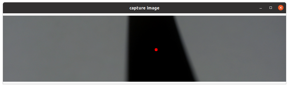
Press Enter and the program automatically saves the image to the image_dataset file and marks the result. The image is named xy_[x coordinate]_[y coordinate]_[uuid].jpg, where the uuid is the unique identifier of the image to avoid the same file name.
According to the above data collection and annotation methods, a certain amount of data is collected, at least 100 pieces of data are recommended for subsequent model training. When the environment or site changes, corresponding pictures can also be collected and trained together to improve the adaptability of the model.
Model selection
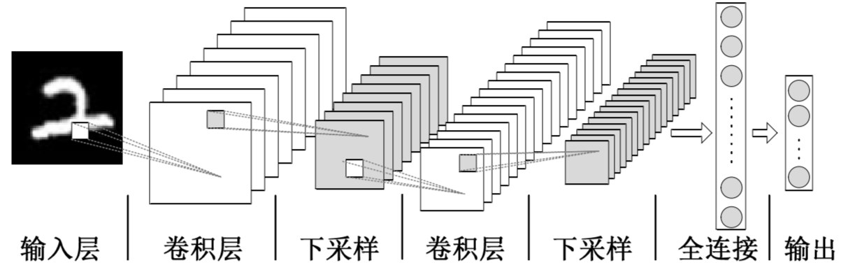
Convolutional Neural Network (CNN) is a deep neural network model that is widely used in image, natural language processing and other fields. In 1998, Lecun et al. proposed a gradient-based backpropagation algorithm for document recognition. In this neural network, the Convolutional Layer plays a crucial role. With the continuous enhancement of computing power, some large CNN networks began to show huge advantages in the field of image. In 2012, Krizhevsky et al proposed AlexNet network structure and won the champion in ImageNet image classification competition with an advantage of 11%. Subsequently, different scholars proposed a series of network structures and constantly updated the achievements of ImageNet, among which the more classic networks include: VGG(Visual Geometry Group), GoogLeNet and ResNet. The convolutional neural network consists of input layer, convolutional layer, pooling layer, fully connected layer and output layer, and its structure is as follows:
Considering the maturity of the model and the hardware requirements of the training model on CPU/GPU, ResNet network is selected as the backbone. Residual neural network (ResNet) was proposed by Kaiming He, Xiangyu Zhang, Shaoqing Ren, Jian Sun and others of Microsoft Research, and won the champion in the ImageNet Large Scale Visual Recognition Challenge (ILSVRC) in 2015. ResNet cleverly uses shortcut connection to solve the problem of model degradation in deep networks, and is one of the most widely used CNN feature extraction networks. The ResNet18 structure is as follows:
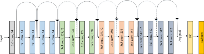
On the Rising Sun X3, the reasoning performance of ResNet18 is as high as 232FPS, and the reasoning performance of ResNet50 is also more than 100FPS. The high frame rate ensures the real-time data processing, which is a necessary condition for the subsequent improvement of speed and the realization of more complex applications. Here, the ResNet18 network structure is used first, and the deeper ResNet50 network structure is considered when the bottleneck is encountered in the later stage. In order to meet the coordinate value x of the output boot line, y, the FC output of the ResNet18 network needs to be changed to 2, that is, the x and y coordinate values of the boot line are directly output. ResNet18 input resolution is 224x224.
The training framework uses the recently hot pytorch, here install the CPU version pytorch, if there is a GPU card on the hardware can choose the GPU version pytorch. The installation command is as follows:
pip3 install torch torchvision torchaudio --extra-index-url https://download.pytorch.org/whl/cpu
The PC used for development is a normal laptop with the following configuration:
CPU: Intel i5-7260U
DDR: 8G
OS: ubuntu20.04
Model implementation and training
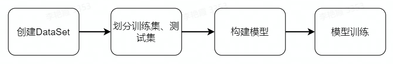
The completion code for this function is located in line_follower/line_follower_model/line_follower_model/training_member_function.py
To create a custom torch.utils.data.Dataset, you need to implement __len__ and __getitem__ methods. Guide line x and y coordinates are obtained by analyzing the file name corresponding to the image (xy_[x coordinates]_[y coordinates]_[uuid].jpg). Since the resolution of the captured image is 960*224 and the input resolution of the model is 224*224, the x direction coordinates need to be scaled first and then normalized. To increase the robustness of the model, color_jitter is added to the raw data.
def get_x(path, width):
    """Gets the x value from the image filename"""
    return (float(int(path.split("_")[1])) * 224.0 / 960.0 - width/2) / (width/2)

def get_y(path, height):
    """Gets the y value from the image filename"""
    return ((224 - float(int(path.split("_")[2]))) - height/2) / (height/2)

class XYDataset(torch.utils.data.Dataset):

    def __init__(self, directory, random_hflips=False):
        self.directory = directory
        self.random_hflips = random_hflips
        self.image_paths = glob.glob(os.path.join(self.directory, '*.jpg'))
        self.color_jitter = transforms.ColorJitter(0.3, 0.3, 0.3, 0.3)

    def __len__(self):
        return len(self.image_paths)

    def __getitem__(self, idx):
        image_path = self.image_paths[idx]

        image = PIL.Image.open(image_path)
        x = float(get_x(os.path.basename(image_path), 224))
        y = float(get_y(os.path.basename(image_path), 224))

        if self.random_hflips:
          if float(np.random.rand(1)) > 0.5:
              image = transforms.functional.hflip(image)
              x = -x

        image = self.color_jitter(image)
        image = transforms.functional.resize(image, (224, 224))
        image = transforms.functional.to_tensor(image)
        image = image.numpy().copy()
        image = torch.from_numpy(image)
        image = transforms.functional.normalize(image, [0.485, 0.456, 0.406], [0.229, 0.224, 0.225])
        return image, torch.tensor([x, y]).float()
Split the data set into a training set and a test set
test_percent = 0.1
num_test = int(test_percent * len(dataset))
train_dataset, test_dataset = torch.utils.data.random_split(dataset, [len(dataset) - num_test, num_test])
Create a data loader to load data into the training and test sets. batch_size is selected according to the computer performance and convergence speed. Generally speaking, a large batch_size requires a larger memory capacity, and the jitter during the convergence process will be smaller. Select 24 here.
 train_loader = torch.utils.data.DataLoader(
    train_dataset,
    batch_size=24,
    shuffle=True,
    num_workers=0
)

test_loader = torch.utils.data.DataLoader(
    test_dataset,
    batch_size=24,
    shuffle=True,
    num_workers=0
)
PyTorch TorchVison already has a ResNet18 model, which can be directly used to modify it. The default ResNet18 model FC output size is 512, here it is modified to 2, that is, corresponding to the coordinate values of x and y.
# Create the ResNet18 model, select the pre-trained model here, and change the fc output to 2, that is, the x and y coordinate values.
model = models.resnet18(pretrained=True)
model.fc = torch.nn.Linear(512, 2)
device = torch.device('cpu')
model = model.to(device)
For model training, the number of iterations was set to 100, the initial loss was set to 1e9, the adam optimization method was adopted, and the model with the smallest loss on the test set was saved.
NUM_EPOCHS = 100
BEST_MODEL_PATH = 'best_steering_model_xy.pth'
best_loss = 1e9

optimizer = optim.Adam(model.parameters())

for epoch in range(NUM_EPOCHS):

    model.train()
    train_loss = 0.0
    for images, labels in iter(train_loader):
        images = images.to(device)
        labels = labels.to(device)
        optimizer.zero_grad()
        outputs = model(images)
        loss = F.mse_loss(outputs, labels)
        train_loss += float(loss)
        loss.backward()
        optimizer.step()
    train_loss /= len(train_loader)

    model.eval()
    test_loss = 0.0
    for images, labels in iter(test_loader):
        images = images.to(device)
        labels = labels.to(device)
        outputs = model(images)
        loss = F.mse_loss(outputs, labels)
        test_loss += float(loss)
    test_loss /= len(test_loader)

    print('%f, %f' % (train_loss, test_loss))
    if test_loss < best_loss:
        print("save")
        torch.save(model.state_dict(), BEST_MODEL_PATH)
        best_loss = test_loss
Run on PC
source  /opt/ros/foxy/local_setup.bash

colcon build --packages-select line_follower_model

source install/local_setup.bash

ros2 run line_follower_model training
Model Convert
If the floating point model trained by pytorch runs directly on the Rising Sun X3 PI, the efficiency will be very low. In order to improve the operating efficiency and exert the 5T computing power of BPU, it is necessary to carry out the operation of the floating point model turning point model.
The completion code for this function is located at line_follower/line_follower_model/line_follower_model/generate_onnx_member_function.py
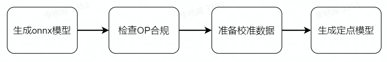
The main steps are as follows:
①pytorch model generates onnx model. Currently, opset_version 10 and 11 are supported, and the onnx code is generated as follows:
import torchvision
import torch

model = torchvision.models.resnet18(pretrained=False)
model.fc = torch.nn.Linear(512,2)
model.load_state_dict(torch.load('./best_line_follower_model_xy.pth'))
device = torch.device('cpu')
model = model.to(device)
model.eval()
x = torch.randn(1, 3, 224, 224, requires_grad=True)
torch_out = model(x)
torch.onnx.export(model,
                  x,
                  "./best_line_follower_model_xy.onnx",
                  export_params=True,
                  opset_version=11,
                  do_constant_folding=True,
                  input_names=['input'],
                  output_names=['output'])
Running mode: ros2 run line_follower_model generate_onnx. After running, best_line_follower_model_xy.onnx model is generated in the current directory.
② Floating-point model generates fixed-point model
The completion code for this function is located at line_follower/10_model_convert
The OE package directory structure is as follows:
.
├── bsp
│   └── X3J3-Img-PL2.2-V1.1.0-20220324.tgz
├── ddk
│   ├── package
│   ├── samples
│   └── tools
├── doc
│   ├── cn
│   ├── ddk_doc
│   └── en
├── release_note-CN.txt
├── release_note-EN.txt
├── run_docker.sh
└── tools
    ├── 0A_CP210x_USB2UART_Driver.zip
    ├── 0A_PL2302-USB-to-Serial-Comm-Port.zip
    ├── 0A_PL2303-M_LogoDriver_Setup_v202_20200527.zip
    ├── 0B_hbupdate_burn_secure-key1.zip
    ├── 0B_hbupdate_linux_cli_v1.1.tgz
    ├── 0B_hbupdate_linux_gui_v1.1.tgz
    ├── 0B_hbupdate_mac_v1.0.5.app.tar.gz
    └── 0B_hbupdate_win64_v1.1.zip
Copy 10_model_convert from the project to the AI toolchain OE package ddk/samples/ai_toolchain/horizon_model_convert_sample/03_classification/ directory
Copy the image_dataset folder containing the data in the data collection step to ddk/samples/ai_toolchain/horizon_model_convert_sample/03_classification/10_model_convert/ In the mapper/ directory, about 100 pieces of data are reserved for calibration.
Load the ai toolchain docker and run it in the OE package root directory:
sh run_docker.sh /data/
Generate calibration data. The calibration data generated in this step is mainly used for the calibration of the next model compilation, and part of the data of the training model can be used. There is no special requirement, as long as the standard is correct, the number should be about 100 pieces.
Execute.
cd ddk/samples/ai_toolchain/horizon_model_convert_sample/03_classification/10_model_convert/mapper
sh 02_preprocess.sh
Results
③ Model compilation
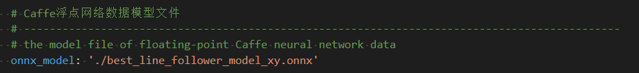
This step will generate a fixed-point model file, and several key points of the 10_model_convert/mapper /resnet18_config.yaml configuration file need to be validated before compiling.
onnx_model: Specifies the path of the onnx model to be converted, note the path within docker:
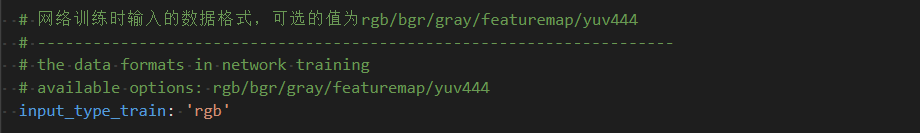
input_type_train: data format during training, because the previous pytorch training used rgb format, here fill in rgb:
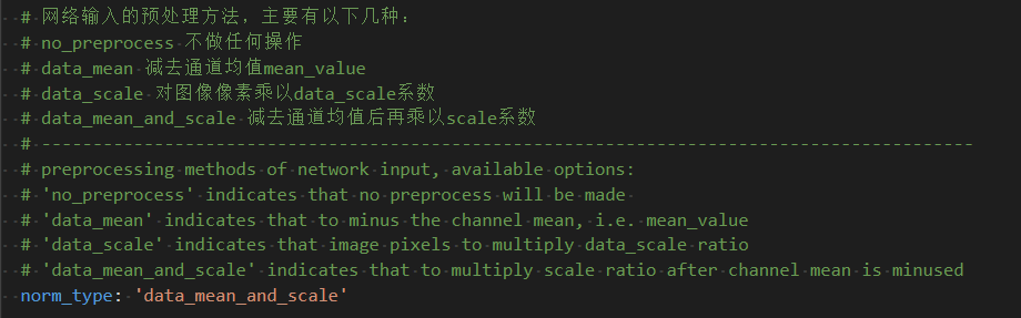
norm_type: normalized, consistent with pytorch training, set to data_mean_and_scale:
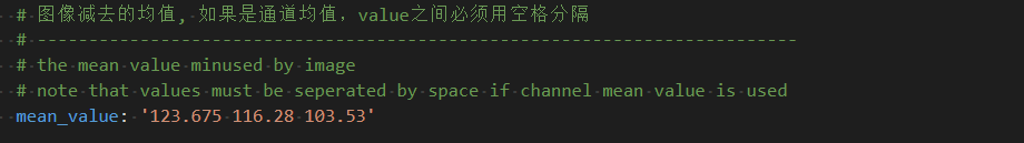
mean_value: corresponds to the normalized parameter, which is the same as the pytorch training, and note that it is multiplied by 255:
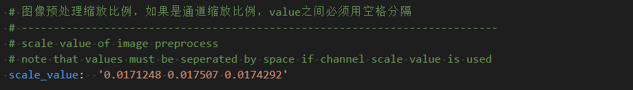
scale_value: corresponds to the normalized parameter, which is the same as the pytorch training, but note that it is multiplied by 255:
The complete configuration file is located at line_follower/10_model_convert/mapper/resnet18_config.yaml
④ Operation
cd ddk/samples/ai_toolchain/horizon_model_convert_sample/03_classification/10_model_convert/mapper
sh 03_build.sh
The results are as follows:
End-to-end deployment
The fixed point model that can run on X3pi BPU has been obtained through the previous model transformation. How to deploy it on X3pi to realize the complete set of functions such as image acquisition, model inference and motion control? This is based on the Hobot DNN implementation in TogetherROS. Hobot DNN is the TogetherROS in-stack algorithm-inference framework that uses the BPU processor for AI inference in the Horizon Rising Sun X3 to provide a simpler and easier interface for integrated model development for robot applications, including model management, input processing based on model descriptions, and result analysis. And model output memory allocation management and other functions.
Inheriting DnnNode implements the necessary interfaces. Public inheritance is used here, where the interfaces that must be implemented are:
The SetNodePara() command is used to configure model parameters, such as model path and model name.
②SetOutputParser() is used to parse the model inference output;
PostProcess(const std::shared_ptr &outputs) is used for further use of post-processing results.
class LineFollowerPerceptionNode : public DnnNode {
 public:
  LineFollowerPerceptionNode(const std::string& node_name,
                        const NodeOptions &options = NodeOptions());
  ~LineFollowerPerceptionNode() override;

 protected:
  int SetNodePara() override;
  int SetOutputParser() override;
  int PostProcess(const std::shared_ptr<DnnNodeOutput> &outputs) override;

 private:
  int Predict(std::vector<std::shared_ptr<DNNInput>> &dnn_inputs,
              const std::shared_ptr<DnnNodeOutput> &output,
              const std::shared_ptr<std::vector<hbDNNRoi>> rois);
  void subscription_callback(
    const hbm_img_msgs::msg::HbmMsg1080P::SharedPtr msg);
};
SetNodePara() sets the store path for the model, the name of the model, the type of inference task (synchronous/asynchronous), and the number of threads when inference is performed as follows:
int LineFollowerPerceptionNode::SetNodePara() {
  if (!dnn_node_para_ptr_) {
    return -1;
  }
  RCLCPP_ERROR(rclcpp::get_logger("LineFollowerPerceptionNode"), "path:%s\n", model_path_.c_str());
  RCLCPP_ERROR(rclcpp::get_logger("LineFollowerPerceptionNode"), "name:%s\n", model_name_.c_str());
  dnn_node_para_ptr_->model_file = model_path_;
  dnn_node_para_ptr_->model_name = model_name_;
  dnn_node_para_ptr_->model_task_type = model_task_type_;
  dnn_node_para_ptr_->task_num = 4;
  return 0;
}
SetOutputParser() sets LineCoordinateParser as the model inference result parsing class. The Parse() member function of this class parses the inference result, because the trained ResNet18 model outputs x and y coordinates. Here, you can read (tensor.sysMem[0].viraddr)[0] and (tensor.sysMem[0].viraddr)[1] as float to get the normalized coordinate value, and reverse normalize to get the pixel value.
class LineCoordinateParser
  : public SingleBranchOutputParser<LineCoordinateResult> {
 public:
  LineCoordinateParser() {}
  ~LineCoordinateParser() {}
  int32_t Parse(
      std::shared_ptr<LineCoordinateResult>& output,
      std::vector<std::shared_ptr<InputDescription>>& input_descriptions,
      std::shared_ptr<OutputDescription>& output_description,
      std::shared_ptr<DNNTensor>& output_tensor) override;
};

int32_t LineCoordinateParser::Parse(
    std::shared_ptr<LineCoordinateResult> &output,
    std::vector<std::shared_ptr<InputDescription>> &input_descriptions,
    std::shared_ptr<OutputDescription> &output_description,
    std::shared_ptr<DNNTensor> &output_tensor) {
  if (!output_tensor) {
    RCLCPP_ERROR(rclcpp::get_logger("LineFollowerPerceptionNode"), "invalid out tensor");
    rclcpp::shutdown();
  }
  std::shared_ptr<LineCoordinateResult> result;
  if (!output) {
    result = std::make_shared<LineCoordinateResult>();
    output = result;
  } else {
    result = std::dynamic_pointer_cast<LineCoordinateResult>(output);
  }
  DNNTensor &tensor = *output_tensor;
  const int32_t *shape = tensor.properties.validShape.dimensionSize;
  hbSysFlushMem(&(tensor.sysMem[0]), HB_SYS_MEM_CACHE_INVALIDATE);
  float x = reinterpret_cast<float *>(tensor.sysMem[0].virAddr)[0];
  float y = reinterpret_cast<float *>(tensor.sysMem[0].virAddr)[1];
  result->x = (x * 112 + 112) * 960.0 / 224.0;
  result->y = 224 - (y * 112 + 112) + 272 - 112;
  return 0;
}

int LineFollowerPerceptionNode::SetOutputParser() {
  auto model_manage = GetModel();
  if (!model_manage) {
    RCLCPP_ERROR(rclcpp::get_logger("LineFollowerPerceptionNode"), "Invalid model");
    return -1;
  }
  int output_index = model_manage->GetOutputCount() - 1;

  std::shared_ptr<OutputParser> line_coordinate_parser =
      std::make_shared<LineCoordinateParser>();
  model_manage->SetOutputParser(output_index, line_coordinate_parser);

  return 0;
}
PostProcess(const std::shared_ptr &outputs), here we use model inference to publish robot control commands based on x and y coordinate values combined with simple strategies. The message controlling the car is the Twist() in geometry_msgs, which has six variables and has the following meaning:
linear.x: Linear speed in the x direction. The robot takes the x direction directly in front of the car and z direction vertically up the ground, satisfying the right hand rule. Unit m/s;
linear.y: Linear speed in the y direction. The robot takes the x direction directly in front of the car and z direction vertically up the ground, satisfying the right hand rule. Unit m/s;
linear.z: Linear speed in the z direction. The robot takes the x direction directly in front of the car and z direction vertically up the ground, satisfying the right hand rule. Unit m/s;
angular.x: The robot rotates counterclockwise around the x axis, taking the front of the car as the x direction and the vertical ground as the z direction, satisfying the right hand rule. Unit rad/s;
angular.y: The robot rotates counterclockwise around the y axis, taking the x direction directly in front of the car and the z direction vertically up the ground, satisfying the right hand rule. Unit rad/s;
angular.z: The robot rotates counterclockwise around the z axis, taking the x direction directly in front of the car and the z direction vertically up the ground, satisfying the right hand rule. Unit rad/s;
Here the x-direction speed is set to 0.1m/s, and angular.z is set according to the degree of deviation between the x coordinate and the image center coordinate. In order to prevent the rotation speed from being too large, here the coefficient is divided by 300, that is, float angular_z = -1.0 * (X-480) / 300.0. After setting the message content, the pushlish function is called to send the message.
int LineFollowerPerceptionNode::PostProcess(
  const std::shared_ptr<DnnNodeOutput> &outputs) {
  auto result = dynamic_cast<LineCoordinateResult *>(outputs->outputs[0].get());
  int x = result->x;
  int y = result->y;
  RCLCPP_INFO(rclcpp::get_logger("LineFollowerPerceptionNode"),
               "post coor x: %d    y:%d", x, y);
  float angular_z = -1.0 * (x - 480) / 300.0;
  auto message = geometry_msgs::msg::Twist();
  message.linear.x = 0.1;
  message.linear.y = 0.0;
  message.linear.z = 0.0;
  message.angular.x = 0.0;
  message.angular.y = 0.0;
  message.angular.z = angular_z;
  publisher_->publish(message);
  return 0;
}
Once you’ve got the model parsing and motion control, what happens if you get an image and when does that trigger the inference? Familiar subscription is required, “zero-copy” communication is used to reduce system load, image preprocessing is done in the callback function and model inference is triggered. Different from the previous part about data collection, the type of the message subscriber_ subscribes to is <hbm_img_msgs::msg::HbmMsg1080P, and the topic name is “hbmem_img”. The resolution of the image received by the callback function is 960*544. As with the pre-processing of model training, the received image is crop&resize, and then the predict interface is called for inference.
LineFollowerPerceptionNode::LineFollowerPerceptionNode(const std::string& node_name,
                      const NodeOptions& options)
  : DnnNode(node_name, options) {
  this->declare_parameter("model_path", "./resnet18_224x224_nv12.bin");
  this->declare_parameter("model_name", "resnet18_224x224_nv12.bin");
  if (GetParams() == false) {
    RCLCPP_ERROR(this->get_logger(), "LineFollowerPerceptionNode GetParams() failed\n\n");
    return;
  }

  if (Init() != 0) {
    RCLCPP_ERROR(rclcpp::get_logger("LineFollowerPerceptionNode"), "Init failed!");
  }

  publisher_ =
    this->create_publisher<geometry_msgs::msg::Twist>("cmd_vel", 5);

  subscriber_ =
    this->create_subscription_hbmem<hbm_img_msgs::msg::HbmMsg1080P>(
      "hbmem_img",
      10,
      std::bind(&LineFollowerPerceptionNode::subscription_callback,
      this,
      std::placeholders::_1));
}

void LineFollowerPerceptionNode::subscription_callback(
    const hbm_img_msgs::msg::HbmMsg1080P::SharedPtr msg) {
  int ret = 0;
  if (!msg || !rclcpp::ok()) {
    return;
  }

  auto model_manage = GetModel();
  if (!model_manage) {
    RCLCPP_ERROR(rclcpp::get_logger("LineFollowerPerceptionNode"), "Invalid model");
    return;
  }

  hbDNNRoi roi;
  roi.left = 0;
  roi.top = 160;
  roi.right = 960 - 1;
  roi.bottom = 384 - 1;
  hbDNNTensor input_tensor;
  prepare_nv12_tensor_without_padding(reinterpret_cast<const char*>(msg->data.data()),
                                      msg->height,
                                      msg->width,
                                      &input_tensor);

  hbDNNTensor output_tensor;
  prepare_nv12_tensor_without_padding(224, 224, &output_tensor);


  hbDNNResizeCtrlParam ctrl = {
      HB_BPU_CORE_0, 0, HB_DNN_RESIZE_TYPE_BILINEAR, 0, 0, 0, 0};
  hbDNNTaskHandle_t task_handle = nullptr;
  hbDNNResize(&task_handle, &output_tensor, &input_tensor, &roi, &ctrl);
  ret = hbDNNWaitTaskDone(task_handle, 0);
  if (0 != ret) {
    RCLCPP_ERROR(rclcpp::get_logger("LineFollowerPerceptionNode"), "hbDNNWaitTaskDone failed!");
    hbSysFreeMem(&(input_tensor.sysMem[0]));
    hbSysFreeMem(&(output_tensor.sysMem[0]));
  }
  hbDNNReleaseTask(task_handle);
  if (0 != ret) {
    RCLCPP_ERROR(rclcpp::get_logger("LineFollowerPerceptionNode"), "release task failed!");
    hbSysFreeMem(&(input_tensor.sysMem[0]));
    hbSysFreeMem(&(output_tensor.sysMem[0]));
  }


  std::shared_ptr<hobot::easy_dnn::NV12PyramidInput> pyramid = nullptr;
  pyramid = hobot::dnn_node::ImageProc::GetNV12PyramidFromNV12Img(
      reinterpret_cast<const char*>(output_tensor.sysMem[0].virAddr),
      224,
      224,
      224,
      224);
  if (!pyramid) {
    RCLCPP_ERROR(rclcpp::get_logger("LineFollowerPerceptionNode"), "Get Nv12 pym fail!");
    return;
  }
  std::vector<std::shared_ptr<DNNInput>> inputs;
  auto rois = std::make_shared<std::vector<hbDNNRoi>>();
  roi.left = 0;
  roi.top = 0;
  roi.right = 224;
  roi.bottom = 224;
  rois->push_back(roi);

  for (size_t i = 0; i < rois->size(); i++) {
    for (int32_t j = 0; j < model_manage->GetInputCount(); j++) {
      inputs.push_back(pyramid);
    }
  }

  auto dnn_output = std::shared_ptr<DnnNodeOutput>();

  ret = Predict(inputs, dnn_output, rois);

  ret = hbSysFreeMem(&(input_tensor.sysMem[0]));
  if (ret != 0) {
    RCLCPP_ERROR(rclcpp::get_logger("LineFollowerPerceptionNode"),
                 "Free input_tensor mem failed!");
    hbSysFreeMem(&(output_tensor.sysMem[0]));
  }
  ret = hbSysFreeMem(&(output_tensor.sysMem[0]));
  if (ret != 0) {
    RCLCPP_ERROR(rclcpp::get_logger("LineFollowerPerceptionNode"),
                 "Free output_tensor mem failed!");
  }
}
OK, done the board data acquisition, model reasoning, result analysis, motion control. For details, see line_follower/line_follower_perception/src/line_follower_perception.cpp
Now it’s time to see what happens.
Copy the line_follower_perception folder and the compiled fixed-point model to the board:
source /opt/tros/local_setup.bash

clocon build --packages-select line_follower_perception
After compiling, specify the path and name of the model with the model_path and model_name parameters:
source install/local_setup.bash
ros2 run line_follower_perception line_follower_perception --ros-args -p model_path:=./resnet18_224x224_nv12.bin -p model_name:=resnet18_224x224_nv12 &
拷贝/opt/tros/share/mipi_cam/launch/mipi_cam.launch.py至当前目录,将输出数据类型改为nv12,通信方式改为“shared_mem”以使能“zero-copy”:
run:
source /opt/tros/local_setup.bash
ros2 launch ./mipi_cam.launch.py &
Finally, enter the motion control package of the car and run the originbot_base:
source install/local_setup.bash
ros2 run originbot_base originbot_base
You can see that the car has begun to patrol the line:
Reference
https://developer.horizon.ai/api/v1/fileData/TogetherROS/index.html www.originbot.org https://arxiv.org/pdf/1512.03385.pdf https://pytorch.org/get-started/locally/ https://docs.ros.org/en/foxy/Tutorials